Many good arrows died assembling the above diagram.
Trying to figure out how to use the microcontrollers SPI and Timer modules to accomplish the protocol described above is easier written than done. I know that because I wrote it, but I haven't managed to do it.
Implementing the protocol has two distinct stages: detecting when something should happen, and responding appropriately. There's a third consideration, doing it in a timely fashion.
I've written the CD32 shifting protocol in C bit-banged, but I'm only getting six of the seven buttons reported by Amiga Test Kit, and they're all showing up as the next button in sequence, and not very reliably at that. No matter what manual approach I try, I can't simultaneously detect when the Amiga is polling the pad, and change the directionality of all the pins and present the correct responses in time to the clock. This is why hardware modules for this kind of thing exist after all.
Replacing all the bidirectional pin resistors with 47R made everything a lot more stable, and now my buttons are showing up in the correct sequence, except for the first button which isn't presented in time.
One obvious-in-retrospect improvement I implemented was to calculate what I call the 'CD32 reply word' in advance - this is the 16-bit value that would be shifted out of
9 FIRE2OUT/DATAOUT in the correct MSB bit order the CD32 expects to see. Originally, I was constructing this word on-demand when
5 JOYMODE fell, which compiled into a horrific pile of shifts. Constructing it in advance within the infrequent directional update interrupt is a smart move. However, I awarded myself a cup of very sweet tea for deciding the correct time to swizzle it into the CD32 reply word form was when I interpreting the completed SPI response from the PS2 pad. Specifically, if I specified the CD32 reply word as a
struct containing bitfields, the word would be created in position with very neat C code, while maintaining its portability and accessibility as a reusable library.
Looking at the execution times of instructions and the time the PIC requires to respond to the interrupt caused by the rising clock edges, this is really tight stuff. I'd like to use the SPI module, but I'm not convinced I can.
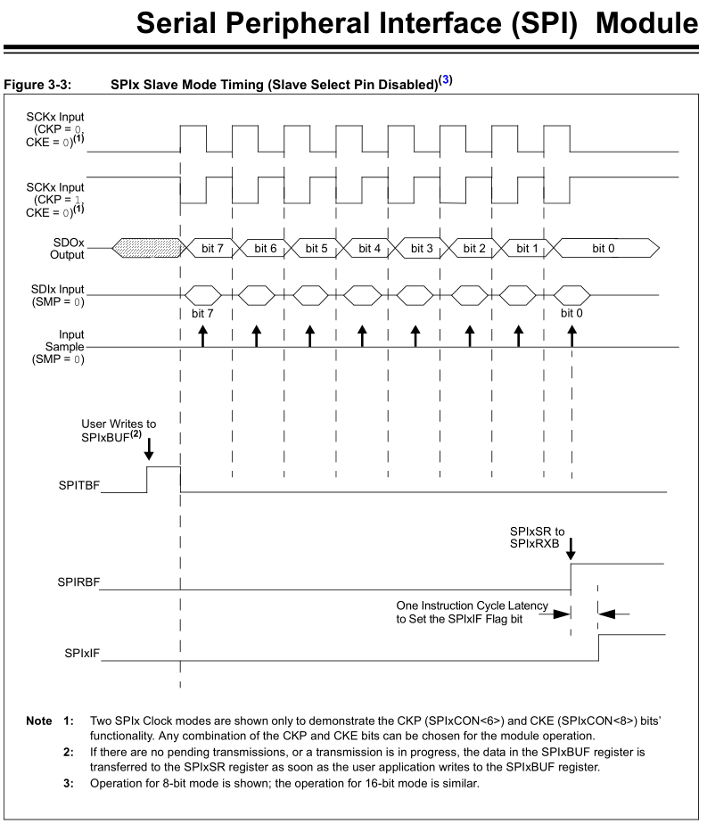
What I want to happen is that the Blue button state is presented on the output immediately when
5 JOYMODE falls, to be replaced by the Red state on the first rising edge of
6 FIRE1OUT/CLOCKIN. In the diagrams in the
Reference Manual chapter for SPI, the outgoing data line is indeterminate until the first clock descending edge, but I can't guarantee that I'll see that because (Amiga Test Kit code discounted) there's no guarantee in the order of events of
6 FIRE1OUT/CLOCKIN and
5 JOYMODE falling. My button states might be presented correctly, or off by one button again.
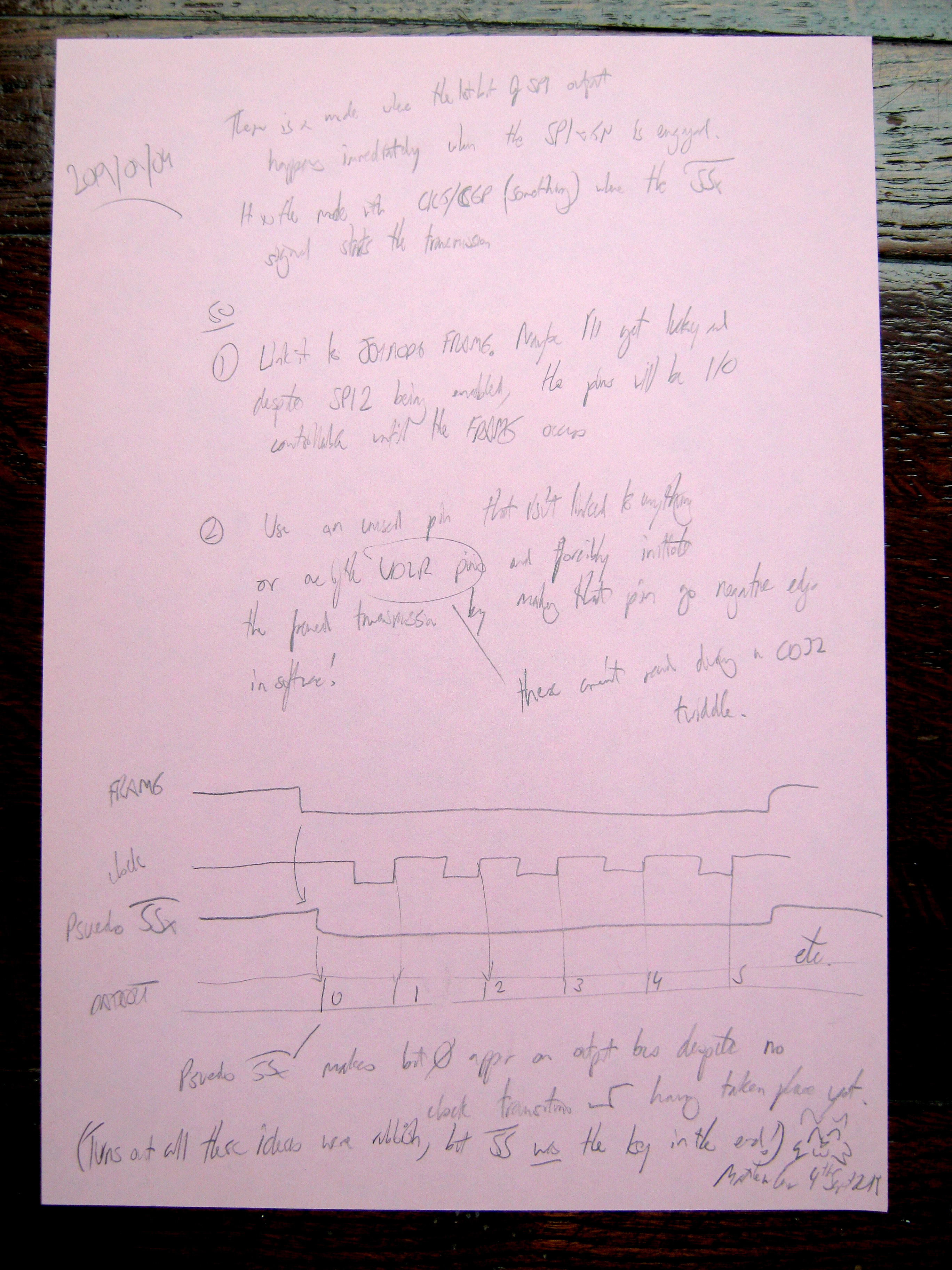
I decided to sleep on it. But before I did, I sketched this:
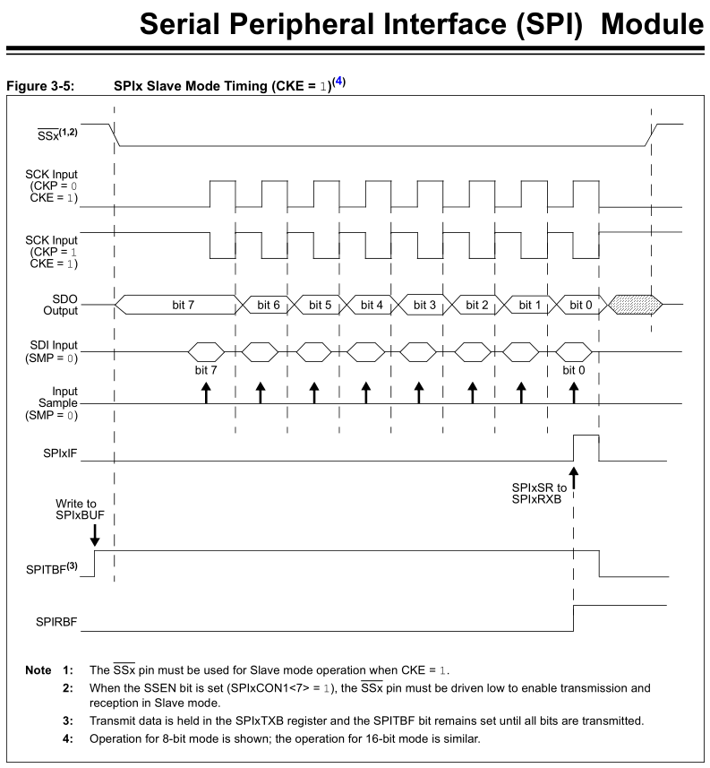
These two new approaches use one of the other SPI modes which presents the first output bit immediately on initalising the SPI module and shifts bits out on ascending clock edges, exactly what I want to happen. However, this relies on a pin being dedicated to the SPI frame signal. This is fine, except if I use
5 JOYMODE as the SPI framing signal, the SPI buffer won't have the correct word in it to send, I think. I'll only know the correct word to send when the frame begins, and by then it's too late! I'm not sure the SPI buffer would like the content of its buffer being overwritten repeatedly before it's ever sent. Or perhaps mid-sending.
The second note says I could start of the SPI frame in this mode by using one of the unused pins of the microcontroller, explicitly starting the SPI frame with a hardware trigger triggered in software. The sequence would be
5 JOYMODE falls, interrupt is fired, word is placed in buffer, extra pin is pulled low, SPI hardware is triggered. Could work?