I'm going to need tea. And diagrams. Lots and lots of diagrams and tea.
First, I need to identify what operations the Amiga is going to perform, and the responses it expects. The tables and diagrams from Gerd Kautzmann's CD32 controller page are a good start, but I'd like them in linear timing diagram form.
Here it is.
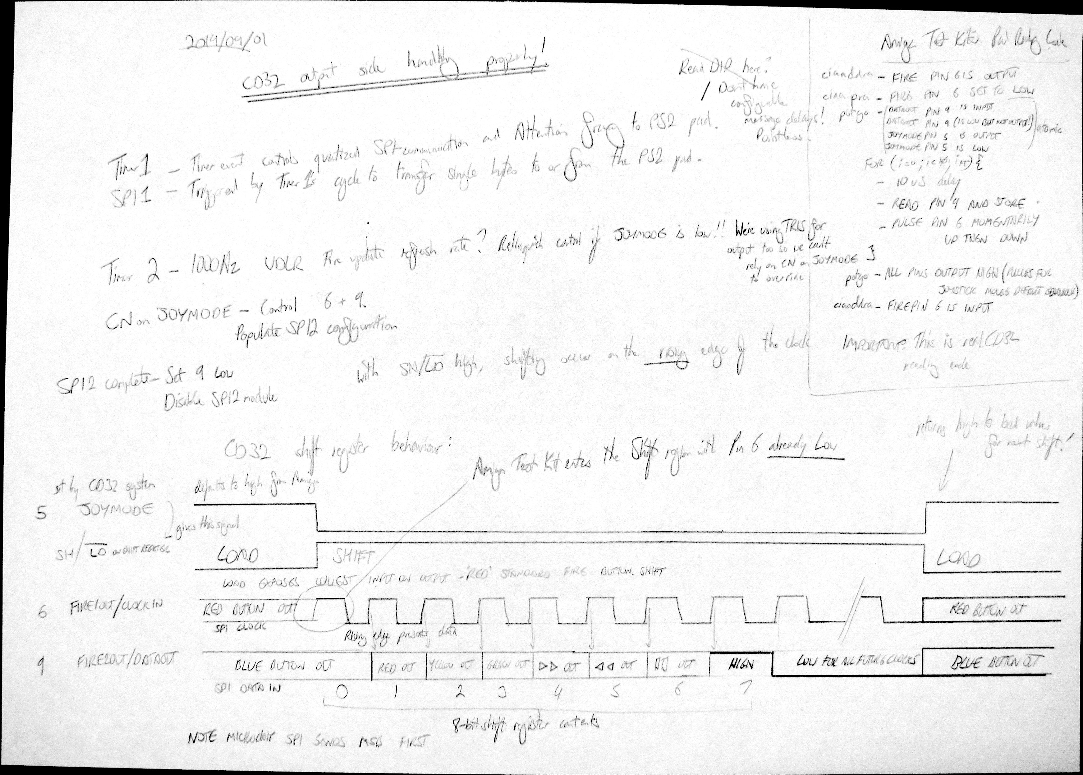
The diagram at the bottom shows the states of pins 5, 6 and 9 from the CD32 game port during a controller poll.
• While
5 JOYMODE/FRAME is high, the controller acts as a two-button, closed-switch joystick. In this state, the state of Red and Blue are output from the controller immediately, at all times on pins
6 FIRE1OUT/CLOCKIN and
9 FIRE2OUT/DATAOUT. (I also just noticed that this pin is left floating if connected to a system that doesn't use pin 5 according to Kautzmann.)
• When
5 JOYMODE/FRAME goes low, the shift register captures its inputs and presents the frozen Blue value on
9 FIRE2OUT/DATAOUT. Pin
6 FIRE1OUT/CLOCKIN becomes an input to the pad.
• The output of pin
9 FIRE1OUT/DATAOUT is constant until a rising edge on pin
6 FIRE1OUT/CLOCKIN, where it cycles to the next button input in this order: Red, Yellow, Green, FF, Rew, Pause, 1, 0, 0, 0...
• The shifting is terminated if
5 JOYMODE/FRAME rises, the shift register returns to loading mode, with instantaneous Red and Blue outputs on pins
6 FIRE1OUT/CLOCKIN and
9 FIRE2OUT/DATAOUT.
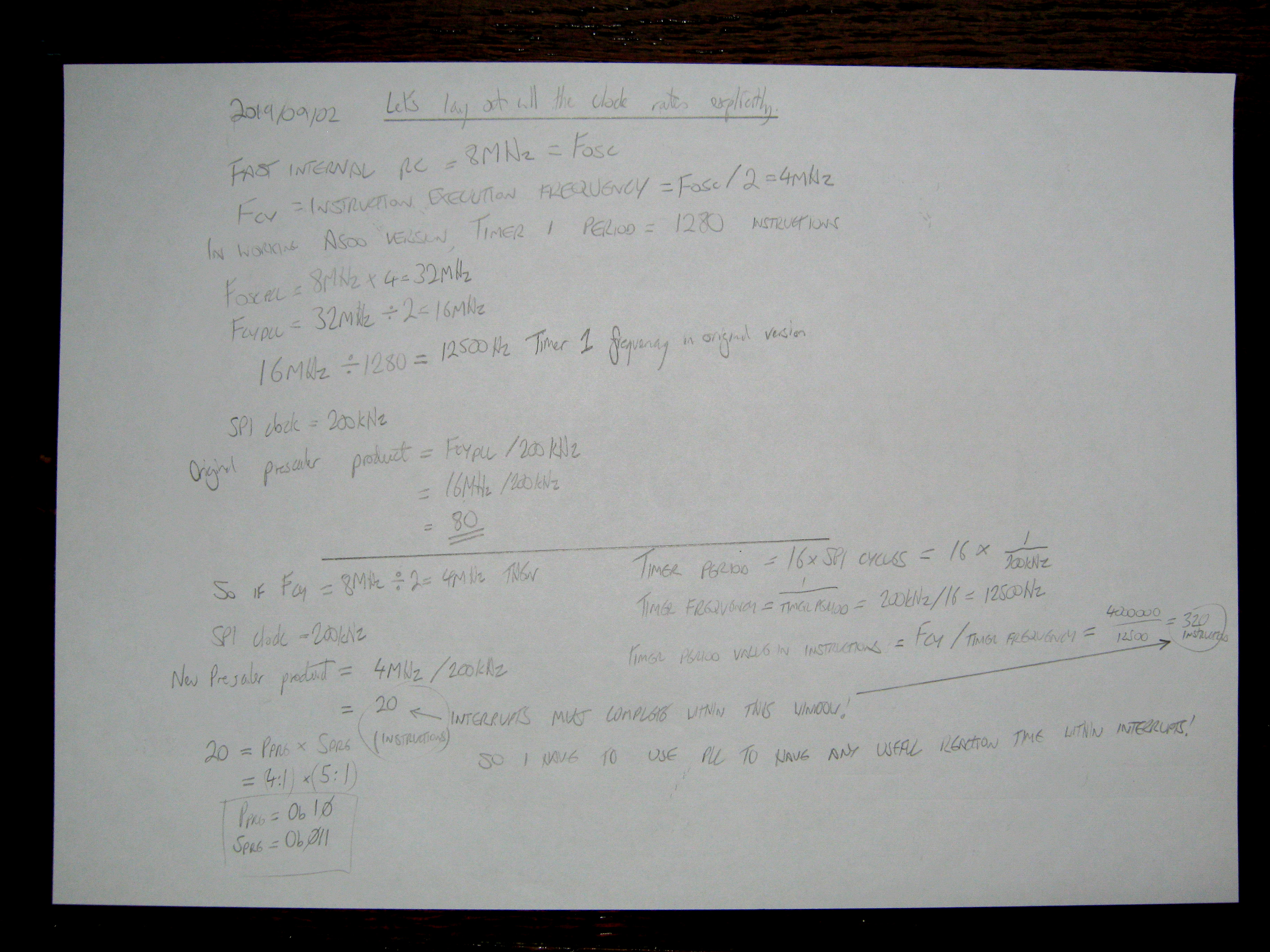
My notes here show my plan.
• Timer1 controls the quantized SPI communication and Attention framing to the PS2 pad.
• SPI1 is triggered by Timer1's cycle to transfer single bytes to or from the PS2 pad.
• Timer2 is a 1000Hz interrupt to ensure a rapid update of the directional output at all times. If
JOYMODE is low, do not manipulate the fire buttons.
• CN interrupt on
5 JOYMODE falling takes control of
6 FIRE1OUT/CLOCKIN and
9 FIRE2OUT/DATAOUT for shift communication. SPI2 may be used to perform the shift communication. If I do this, I have to remember the SPI module will shift out values MSB first.
The issues here are I have to be able tell when the communication is finished - the Amiga may request an arbitrary number of shifted values: enough to read all the buttons, too many and retrieving the infinite zeroes, or abort after reading the colour buttons. I have to detect this event and transform back into a two-button joystick.
There's two good sources of information I can use to learn more about the way the Amiga reads CD32 pads. Throughout these notes I've repeatedly said that Amiga software plays fast and loose with pretty much every part of the system, there are no standard ways to read the game port, keyboard or floppy drive, and if there were, programmers wouldn't use them in the pursuit of speed or plain ignorance. That is true, as far as I know, but for the later OS revisions for the A1200 and CD32 onwards, a module named
lowlevel.library was included in ROM to allow the reading of the CD32 joypad. Documentation is
here. I could disassemble this routine and see exactly what the Amiga attempts to do in the manufacturer-specified ideal reality.
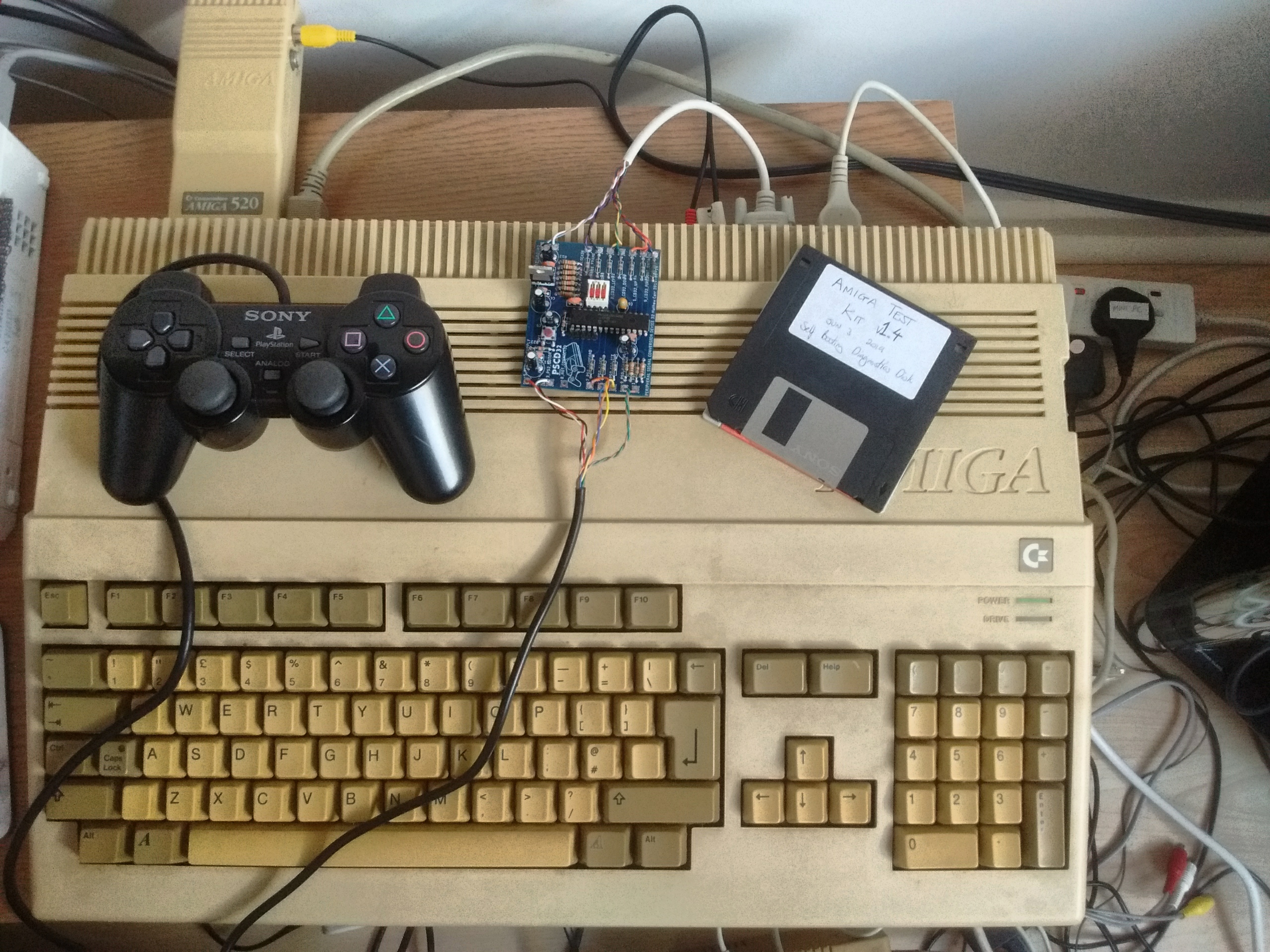
Another, much faster alternative would be to simply
look at the source code to Amiga Test Kit (it's public domain). It'll have comments and stuff. It won't be the same as the Commodore library implementation, but since it's meant to test pads, it ought to be very close to the correct way to read real, existing pads, and it'll be compatible with the A500.
Let's have a look.
/* Read gamepad button state of specified port using specified ciaa address. */
static uint32_t read_gamepad(uint8_t port, volatile struct amiga_cia *_ciaa)
{
unsigned int i, j;
uint32_t state = 0;
/* Pin 6 clocks the shift register (74LS165). Set as output, LOW, before
* we enable the pad's shift-register mode. */
_ciaa->ddra |= CIAAPRA_FIR0 << port;
_ciaa->pra &= ~(CIAAPRA_FIR0 << port);
/* Port pin 5 enables the shift register. Set as output, LOW. Port pin 9
* is the shift-register output ('165 pin 9). Set it as input. */
cust->potgo = port ? 0x2f00 : 0xf200;
/* Probe 7 buttons (B0-B6), plus 3 ID bits (B7-B9).
* B7 = '165 pin 11 (parallel input A) = FALSE (pulled high)
* B8+ = '165 pin 10 (serial input) = TRUE (pulled low) */
for (i = 0; i < 10; i++) {
/* Delay for 8 CIA clocks (~10us). */
for (j = 0; j < 8; j++)
(void)_ciaa->pra;
/* Read the shift-register output (port pin 9). */
if (!(cust->potinp & (port ? 0x4000 : 0x0400)))
state |= 1u << i;
/* Clock the shift register: port pin 6 pulsed HIGH. */
_ciaa->pra |= CIAAPRA_FIR0 << port;
_ciaa->pra &= ~(CIAAPRA_FIR0 << port);
}
/* Return the port to joystick/mouse mode. */
cust->potgo = 0xff00;
_ciaa->ddra &= ~(CIAAPRA_FIR0 << port);
return state;
}
From this I can find that
6 FIRE1OUT/CLOCKIN is pulled low immediately before
5 JOYMODE is pulled low. The pad's output on
9 FIRE2OUT/DATAOUT is sampled by the Amiga at some point during the low phase of the clock cycle, after which it is immediately raised momentarily.
This means we cannot rely on there being a falling edge present on the
6 FIRE1OUT/CLOCKIN line. This is important.