The Man With The Plan
Alright, my approach is THIS! *slams evidence on table, dramatic music plays*
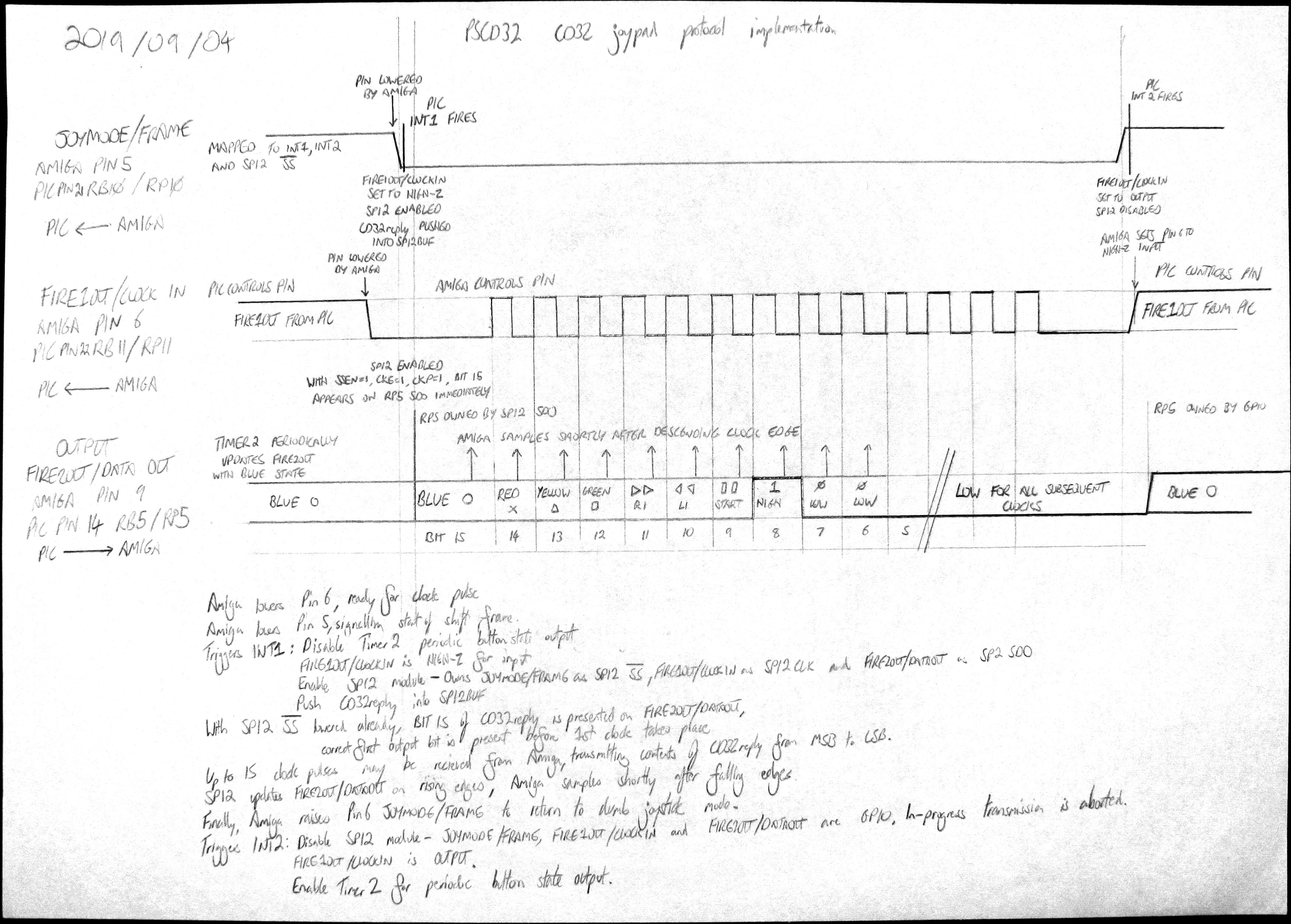
 • Amiga lowers 6 FIRE1OUT/CLOCKIN ready for clock pulse.
• Amiga lowers 5 JOYMODE, singalling start of shift frame.
• Triggers INT1:
• • Disable Timer2 periodic directional button update.
• • 6 FIRE1OUT/CLOCKIN is High-Z for input.
• • Enable SPI2 module - owns 5 JOYMODE as SPI2 !SS, 6 FIRE1OUT/CLOCKIN as SPI2 CLK and 9 FIRE2OUT/DATAOUT as SPI2 SDO.
• • Push CD32 reply word into SPI2BUF.
• With SPI2 !SS lowered already, bit 1 of CD32 reply word is presented on 9 FIRE2OUT/DATAOUT, correct first output bit is present before 1st clock pulse takes place.
• Up to 15 clock pulses may be received from the Amiga, transmitting contents of CD32 reply word from MSB to LSB. There's no reason why the Amiga would clock further than this, the data is meaningless, unless you're using software which expects something other than a CD32 pad to be present, in which case why are you using it with a PSCD32?
• SPI2 updates 9 FIRE2OUT/DATAOUT on rising edges, Amiga samples shortly after falling edges.
• Finally, Amiga raises 5 JOYMODE to return to dumb joystick mode.
• Triggers INT2:
• • Disable SPI2 module - 5 JOYMODE, 6 FIRE1OUT/CLOCKIN and 9 FIRE2OUT/DATAOUT are GPIO; in-progress transmission is aborted.
• • 6 FIRE1OUT/CLOCKIN is OUTPUT.
• • Enable Timer2 periodic directional button update.
To be truthful, I'm not 1,000% confident that this ought to work.
• Amiga lowers 6 FIRE1OUT/CLOCKIN ready for clock pulse.
• Amiga lowers 5 JOYMODE, singalling start of shift frame.
• Triggers INT1:
• • Disable Timer2 periodic directional button update.
• • 6 FIRE1OUT/CLOCKIN is High-Z for input.
• • Enable SPI2 module - owns 5 JOYMODE as SPI2 !SS, 6 FIRE1OUT/CLOCKIN as SPI2 CLK and 9 FIRE2OUT/DATAOUT as SPI2 SDO.
• • Push CD32 reply word into SPI2BUF.
• With SPI2 !SS lowered already, bit 1 of CD32 reply word is presented on 9 FIRE2OUT/DATAOUT, correct first output bit is present before 1st clock pulse takes place.
• Up to 15 clock pulses may be received from the Amiga, transmitting contents of CD32 reply word from MSB to LSB. There's no reason why the Amiga would clock further than this, the data is meaningless, unless you're using software which expects something other than a CD32 pad to be present, in which case why are you using it with a PSCD32?
• SPI2 updates 9 FIRE2OUT/DATAOUT on rising edges, Amiga samples shortly after falling edges.
• Finally, Amiga raises 5 JOYMODE to return to dumb joystick mode.
• Triggers INT2:
• • Disable SPI2 module - 5 JOYMODE, 6 FIRE1OUT/CLOCKIN and 9 FIRE2OUT/DATAOUT are GPIO; in-progress transmission is aborted.
• • 6 FIRE1OUT/CLOCKIN is OUTPUT.
• • Enable Timer2 periodic directional button update.
To be truthful, I'm not 1,000% confident that this ought to work.
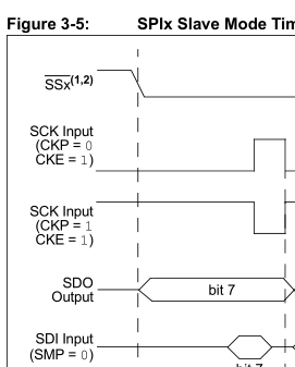
 Looking at the CKE = 1 timing diagram, it strictly seems to be the case that the SPI frame is begun by the falling edge of !SS. However, in reality, either the activation of the SPI module causes various internal buses to fall in the correct way to be read as a falling edge, or the module is designed to allow this behaviour.
One nice effect of this is I don't have to manually mess about with some of the tristate and output settings since when the SPI module is activated by the frame-response interrupt, it takes control of the pins and overrides their output until the SPI module is disabled.
I've specified the SPI2 interrupts to be higher priority than any others I'm using, since it is imperative that the CD32's request be satisfied instantly. This means it can interrupt the PS2 communication sequence, but since the PIC is the master of that communication, the PS2 pad will just be made to wait for the communication to complete when the PIC is able to do so. Since the PS2 pad byte exchange is done in hardware, the clocked data exchange won't be affected by anything on the CD32 side - a whole byte will still be sent at a steady speed, but the PIC won't send the next byte of the message until the CD32 interrupt handler has completed.
Looking at the CKE = 1 timing diagram, it strictly seems to be the case that the SPI frame is begun by the falling edge of !SS. However, in reality, either the activation of the SPI module causes various internal buses to fall in the correct way to be read as a falling edge, or the module is designed to allow this behaviour.
One nice effect of this is I don't have to manually mess about with some of the tristate and output settings since when the SPI module is activated by the frame-response interrupt, it takes control of the pins and overrides their output until the SPI module is disabled.
I've specified the SPI2 interrupts to be higher priority than any others I'm using, since it is imperative that the CD32's request be satisfied instantly. This means it can interrupt the PS2 communication sequence, but since the PIC is the master of that communication, the PS2 pad will just be made to wait for the communication to complete when the PIC is able to do so. Since the PS2 pad byte exchange is done in hardware, the clocked data exchange won't be affected by anything on the CD32 side - a whole byte will still be sent at a steady speed, but the PIC won't send the next byte of the message until the CD32 interrupt handler has completed.