PSCD32 Peripheral Signal Conversion Device
Ingredients:
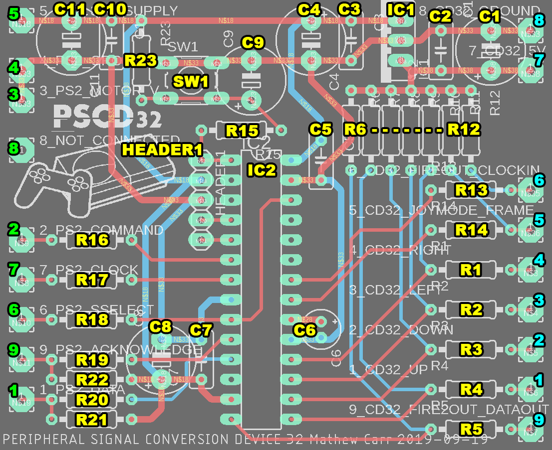
PSCD32 board
Full 9-pin serial extension cable.
8- or 9-pin Playstation controller externsion cable.
PIC24FJ32GA002-I/SP 28-pin 0.3inch skinny DIP package.
MIC2940A3.3 3.3V voltage regulator or equivalent
5-pin 0.1 inch pin header male
6mm tactical switch for reset
Resistors: (all through-hole 1/4 or 1/8 Watt)
1 x 270R (reset)
1 x 8k2 (reset)
9 x 470R (current-limiting resistors)
3 x 47R (current-limiting resistors for Amiga bidirectional pins)
9 x 20k (pull-up resistors for CD32 side, and controller-driven PS2 side)
Capacitors: (all 25V at least, radial through-hole)
4 x 47uF electrolytic
6 x 0.1uF ceramic
1 x 0.1uF electrolytic
1 x 10uF tantalum
You will also need a device capable of programming the PIC24FJ32GA002; the board is set up so that a PICkit2 can be attached to the pin-header with 0.1inch ribbon cables. I use a five-set of peel-away Dupont jumper leads. The MPLAB IDE and the programmer software are both available for Windows, Mac and Linux.
Assembly order:
PIC first, soldering one pin at a time, alternating to other components to avoid overheating
Tactile switch
All resistors
Work from the centre outwards to give you more room to hold the board without risk of damage
Solder spliced cables last
Test the board assembly with a 5V supply such as a USB wall adapter first rather than plugging the device into an Amiga. You should read 3.3V on the PIC supply pins, the PS2 supply pins, and the PS2 supply pins coming out of the connector. If this is not present you have made a mistake.
The PIC should boot up into a safe state where all GPIO pins are high-impedance when first turned on. If unprogrammed, it will remain in this state. It's best to program the PIC for the first time when connected to an external 5V power supply. However, past the initial programming, I've programmed the PIC using the Amiga as a power source many times (iterating while Amiga Test Kit was running on the Amiga).
You cannot program the PSCD32 using Amiga software.
Cable splicing guide:
You will need the 'input' side of the Playstation controller cable that resembles the connectors on the console itself.
You will need the female side of the serial cable that resembles the connector on an Amiga joystick.
Cut your extension cables so you have as much length as you prefer, plus four inches for working with. I prefer to have the Playstation side long and the CD32 side short so that the PSCD32 will rest on the same surface as the CD32 console itself.
Carefully cut the insulation four inches away from the cut to reveal the individual wires.
Strip the two centimetres of insulation from each wire.
Use a multi-meter with probes to allow you to identify which of the wire colours matches each pin in the following pinouts:


It's a good idea to copy these diagrams to paper, writing the wire colours beside each pin numbers as you identify them.
After you have written down all the colours for all the pins, verify your work by repeating the same process with the other side of the extension cable you won't be using. If your colour identifications match up with the pins on the opposite side, you're ready to solder.
Notices
PSCD32 board and case design, runtime software, © Mathew Carr 2019. Iconography ™ Mathew Carr 2019. Site design and content © Mathew Carr 2019.
Software and design licensed to the recipient under the terms of the Apache License 2.0 Link Unless required by applicable law or agreed to in writing, Licensor provides the schematics, software or methods described on this page on an "AS IS" BASIS, WITHOUT WARRANTIES OR CONDITIONS OF ANY KIND, either express or implied, including, without limitation, any warranties or conditions of TITLE, NON-INFRINGEMENT, MERCHANTABILITY, or FITNESS FOR A PARTICULAR PURPOSE. You are solely responsible for determining the appropriateness of using or redistributing the Work and assume any risks associated with Your exercise of permissions under this License.
These software and hardware technologies are not produced, tested, promoted or endorsed by Sony Interactive Entertainment Inc., Commodore International Inc., Commodore-Amiga Inc., Factor 5, or A.U.D.I.O.S.
Trademarks referenced for nominative purposes.