CD32 Gamepad A100 re-engineered documentation
This documentation about the game controll for the Amiga CD32, ist given like it is.
There is now warranty about completeness, use it at your own risk.
Commodore, Amiga, CD32 and maybe even Gamepad are registered Trademarks of any company that owns them in the moment.
The CD32 Gamepad is one of the worst controll devices I ever saw. When
playing CD32 game I usually gets into troubles cause the left handed joystick
replacement thing turns around and stops to work.
There is a good CD32 Gamepad replacement available from CompetitionPro but
it has the same disadvantage like any other Gamepads:
They are all designed for left-handers !
Cause I am a right-handed person, I would prefer to controll the movement
of a game character or spaceship with my right hand. Pressing the fire button
does not need much accuracy, it could be done by the left hand.
I decided to find out, if a normal joystick could be transformed into
a CD32 compatible joystick with all its extra buttons. Unfortunately there
was not any documentation about the CD32 Gamepad available and re-engineeering
turned out to be more difficult than expected.
During a discussion on www.amiga-news.de Jens Schönfeld gave me
a hand drawn schematic and told me some details about the CD32 Gamepad. He
had done some re-engineering to make his new Catweazle MK4 (www.ami.ga )
more CD32 compatible for emulators like UAE.
Here is the documentation I have made out of all this information.There
ar different CD32 Gampad out there, they have some minor changes, to suppress
spikes or wrong signals. The Schematic is still missing some capazitators,
but it should work the way it is drawn.
Pictures
Click on a picture for a detailed view
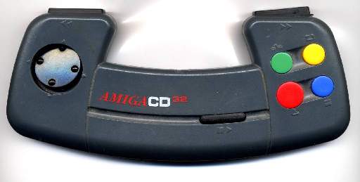
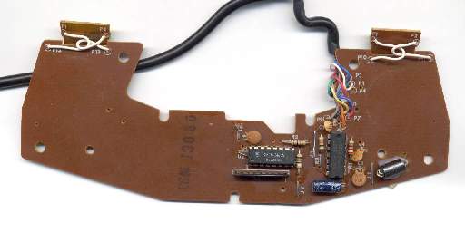
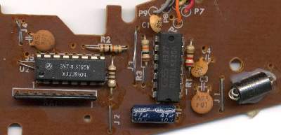
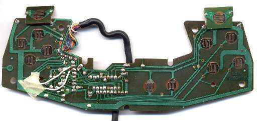
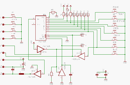


|
| PIN | COLOR V1 | COLOR V2 | DESCRIPTION |
| P1: | WHITE | ORANGE | Joystick Button UP |
| P2: | BLUE | BROWN | Joystick Button DOWN |
| P3: | GREEN | GREEN | Joystick Button LEFT |
| P4: | BROWN | GREY | Joystick Button RIGHT |
| P5: | YELLOW | RED | Paddle POT-X |
| P6: | ORANGE | BLUE | Joystick Button Fire |
| P7: | RED | YELLOW | VCC (+5V) |
| P8: | BLACK | BLACK | GND |
| P9: | GREY | WHITE | Paddle POT-Y |
|
Functions
There are 2 different function modes, the joystick direction switches are used in both modes like in every Amiga compatible joystick.
Joystick Mode (default)
Pot-X (P5) is set to 1 by the CD32, this will set the shift register always to load,
the clock will be ignored and the first bit (blue button) is switched to POT-Y (P9).
POT-X also switches the driver in 74LS125 so the red Button will be conducted to (P6) Joystick Fire.
The Gamepad acts like a normal joystick.
Gamepad Mode
Pot-X (P5) is set to 0 by the CD32, this will switch the driver in 74LS125 to high imepdance an the signal
from the fire button will not be switched to to fire (P6) any more.
With every rising edge on (P6) the state of the Gamepad buttons will be shifted from the inputs of the shift
register over the 74LS125 driver to Pot-Y (P9).
As long as shift/load on the shift register is switched to shift it will shift out the state of the buttons that where loaded before.
| P5: JOYSTICK,LOAD/SHIFT | 1 | 0 | 0 | 0 | 0 | 0 | 0 |
0 | 0 | 0 | 0 | 0 | 0 |
0 | 0 | 0 | 0 | 0 | 0 |
| P6: FIRE,CLK | RED | 1 | 0 | 1 | 0 | 1 | 0 |
1 | 0 | 1 | 0 | 1 | 0 |
1 | 0 | 1 | 0 | 1 | 0 |
| P9: BLUE,SERDATA | BLUE | BLUE | BLUE | RED | RED | YELLOW | YELLOW |
GREEN | GREEN | RIGHT
FRONT | RIGHT
FRONT | LEFT
FRONT | LEFT
FRONT |
PAUSE | PAUSE | 1 | 1 | 0 | 0 |
What is Missing ?
Some capazitators are missing in the schematic, every chip should have a blocking capazitator.
I have still not checked evrything.


