Alright, bit-banging.
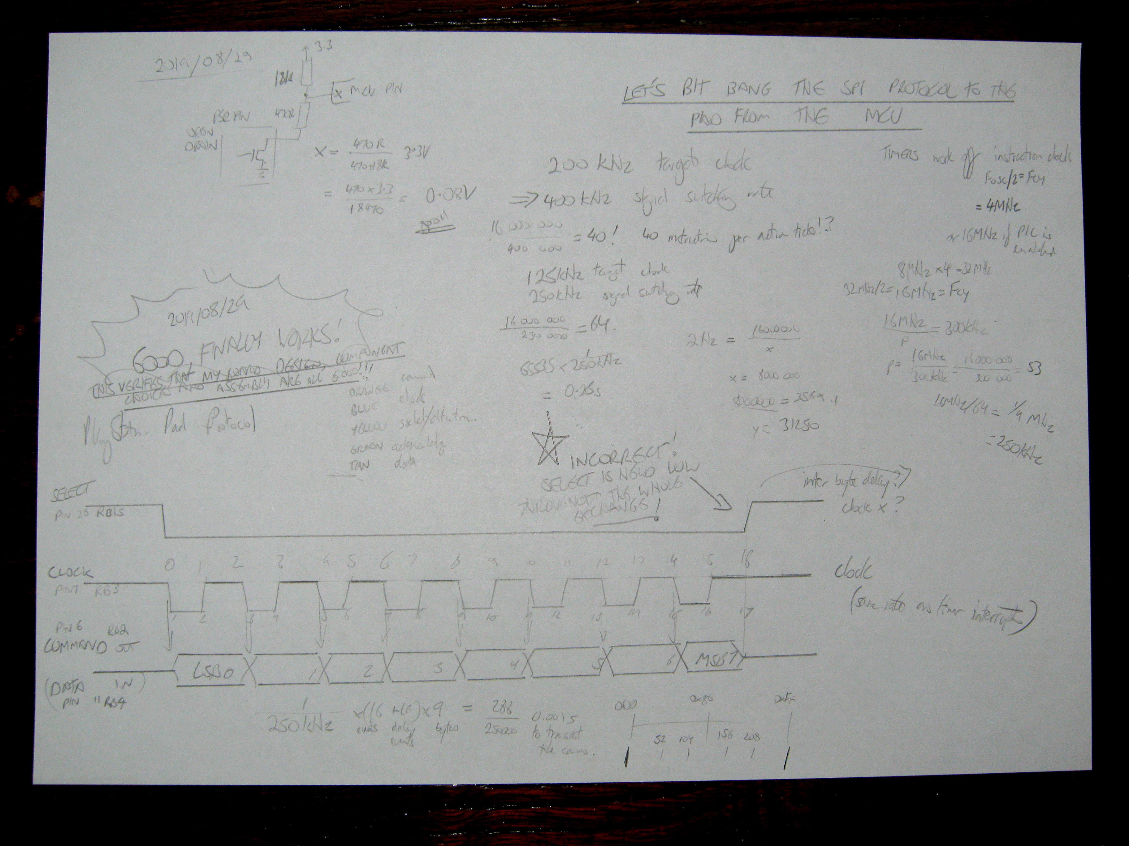
I have the diagram of how the protocol is supposed to look, I know what I'm sending and I know what I'm supposed to be receiving. The PSCD32 is the clocking device, so I can run the protocol as fast or as slow as I like. There's no barriers to manually implementing the protocol on the CPU to manipulate the states of the pins directly.
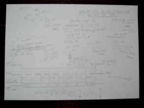
Here's my notes on it, checking that the voltages the pad and MCU are reading are valid logic levels, stepping through the protocol event by event and making sure everything is correct. The clock frequency calculated based on the 40MHz master clock FOSC, everything...
Here's my new approach:
• For a 200KHz SPI clock, there's a protocol event frequency of 400KHz. A new protocol event timer fires at 400KHz to manually step each possible bit transition in the protocol.
• The message abstraction structure now works in terms of protocol events: there's sixteen of these for a single byte exchange, one for each clock state transition, and there's extra padding of CLOCK and COMMAND idle time before, between and after each exchange in case the pad needs some thinking time.
• Each time the protocol event timer fires, it either engages ATTENTION, steps through padding time, a clock descending event where COMMAND data is presented, a clock ascending event where DATA is sampled, or a message end event where ATTENTION is released and the retrieved data analysed.
Alright! It's gross and unnecessary, but it WORKS. Which means it's neither gross, nor unnecessary. It's just functional!
Reading the analogue sticks of an analogue pad is no mystery at all, which is nice. The same attention-poll request 0x01 0x42 is used to query all pad types, and an analogue pad reports a superset of the digital pad's response. If you perform a standard poll message with a nine byte exchange, the analogue sticks and L3/R3 state are included in the response without any further configuration. A digital pad.
Byte
PSCD32
Digital
Analogue
0
0x01
Attention
0xFF
Dummy
0xFF
Dummy
1
0x42
Query Button State
0x41
Digital Controller
0x73
Analogue Controller
2
0x00
Dummy
0x5A
Spacer Byte
0x5A
Spacer Byte
3
0x00
Dummy
data
Buttons 1
data
Buttons 1
4
0x00
Dummy
data
Buttons 2
data
Buttons 2
5
0x00
Dummy
0xFF
Idle
data
Right Stick X
6
0x00
Dummy
0xFF
Idle
data
Right Stick Y
7
0x00
Dummy
0xFF
Idle
data
Left Stick X
8
0x00
Dummy
0xFF
Idle
data
Left Stick Y
The stick values are unsigned 0x00 in the top left and 0xFF in the bottom right.
You can see here that the low nibble of the controller type is reporting how many 16-bit data words the controller may send after the initial three byte exchange.
This is super awesome great news. It confirms a few more things:
• The pad is being powered correctly by the regulator.
• The pad isn't spontaneously resetting (the light is staying on) due to unreliable wiring.
• The pad itself is working at all. This is an original release PS2 pad!
• My messages are being sent to the pad correctly.
• The pad is responding to the PSCD32 in the way I expect.
• I'm analysing the values and getting a sensible response.
• Physically, the resistors I've put inline to reduce the current aren't affecting the incoming or outgoing transmission.
• The pull-up resistors I chose for the input DATA and ACKNOWLEDGE lines are appropriate.
That's a lot of victories.
One thing that's important to bear in mind is that although that PICkit thing is sitting there on the right, it isn't doing anything. This board is completely independent. I could attach batteries on it and have it as a handheld Playstation-pad-using... something. I could package the code together as a feature-rich PIC PS2-reading library right now and use it in all kinds of projects!
I dedicate this victory to tuna, butter, vinegar and pepper buns.
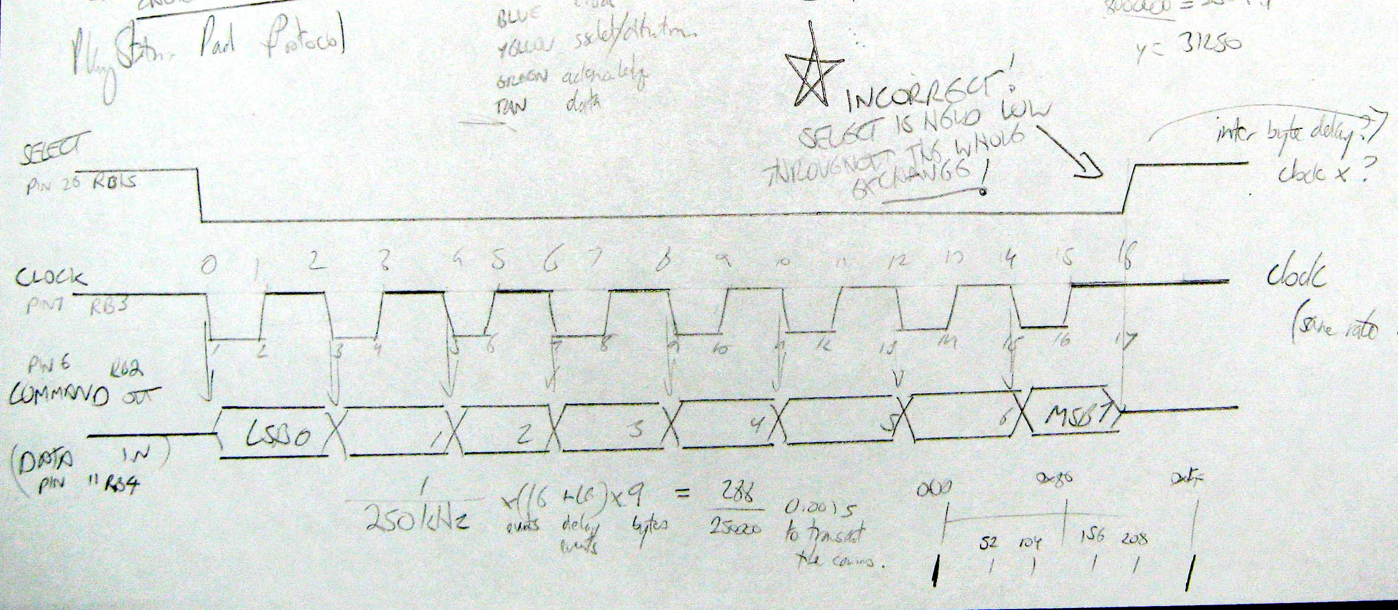
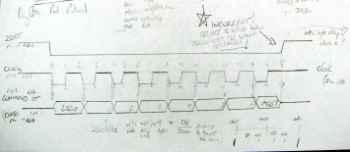
You might have noticed the big ol' star on my previous diagram about my bit-banging.
This is why it's paramount to draw out protocols you're not 100% sure of!
For some reason, I assume that what I wanted was for the ATTENTION to only go low for the duration of the protocol where the byte was being exchanged, and to go high between bytes. But that doesn't make a lot of sense if considered alongside its use as a 'pad active on/off' switch, with the 'off' state returning the pad to its completely idle state ready for a new communication.
Which, in turn means that Framed SPI would be completely useless here!
The Framed SPI used in the Ocelot looks something like this:
Framed SPI would let me instruct the PIC to have the ATTENTION line rise after every complete SPI byte/word transmitted. This is what the TLV5618A expects.
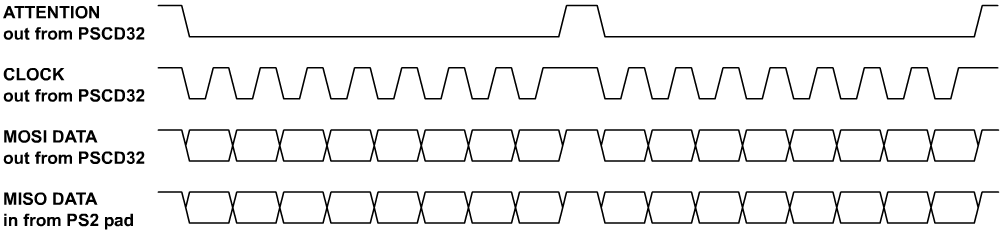
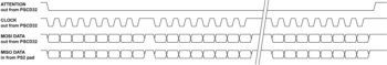
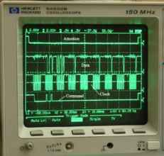
Whereas the correct Playstation protocol looks like this:
The ATTENTION line is asserted continuously through the entire byte exchange, only being raised after all the bytes have been transferred and the message is complete.
So, Framed SPI wouldn't have helped at all. Still doesn't explain why the manual and datasheets recommended for the processor tell you all about something that doesn't work. They should release new revisions of those things, maybe?
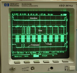
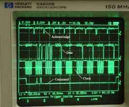
I only noticed this because of one of the oscilloscope photographs on the Curious Inventor's PS2 page.
Thank you!!
Also on this site, it uses the phrase "Note that attention is held low throughout the tranmission". Clearly I didn't. Oops.
Framed SPI aside, the PIC isn't capable of performing the ATTENTION manipulation I need automatically, but I can do it manually if I construct a semi-automatic abstraction around it.
 Here's my notes on it, checking that the voltages the pad and MCU are reading are valid logic levels, stepping through the protocol event by event and making sure everything is correct. The clock frequency calculated based on the 40MHz master clock FOSC, everything...
Here's my new approach:
• For a 200KHz SPI clock, there's a protocol event frequency of 400KHz. A new protocol event timer fires at 400KHz to manually step each possible bit transition in the protocol.
• The message abstraction structure now works in terms of protocol events: there's sixteen of these for a single byte exchange, one for each clock state transition, and there's extra padding of CLOCK and COMMAND idle time before, between and after each exchange in case the pad needs some thinking time.
• Each time the protocol event timer fires, it either engages ATTENTION, steps through padding time, a clock descending event where COMMAND data is presented, a clock ascending event where DATA is sampled, or a message end event where ATTENTION is released and the retrieved data analysed.
Alright! It's gross and unnecessary, but it WORKS. Which means it's neither gross, nor unnecessary. It's just functional!
Reading the analogue sticks of an analogue pad is no mystery at all, which is nice. The same attention-poll request 0x01 0x42 is used to query all pad types, and an analogue pad reports a superset of the digital pad's response. If you perform a standard poll message with a nine byte exchange, the analogue sticks and L3/R3 state are included in the response without any further configuration. A digital pad.
Here's my notes on it, checking that the voltages the pad and MCU are reading are valid logic levels, stepping through the protocol event by event and making sure everything is correct. The clock frequency calculated based on the 40MHz master clock FOSC, everything...
Here's my new approach:
• For a 200KHz SPI clock, there's a protocol event frequency of 400KHz. A new protocol event timer fires at 400KHz to manually step each possible bit transition in the protocol.
• The message abstraction structure now works in terms of protocol events: there's sixteen of these for a single byte exchange, one for each clock state transition, and there's extra padding of CLOCK and COMMAND idle time before, between and after each exchange in case the pad needs some thinking time.
• Each time the protocol event timer fires, it either engages ATTENTION, steps through padding time, a clock descending event where COMMAND data is presented, a clock ascending event where DATA is sampled, or a message end event where ATTENTION is released and the retrieved data analysed.
Alright! It's gross and unnecessary, but it WORKS. Which means it's neither gross, nor unnecessary. It's just functional!
Reading the analogue sticks of an analogue pad is no mystery at all, which is nice. The same attention-poll request 0x01 0x42 is used to query all pad types, and an analogue pad reports a superset of the digital pad's response. If you perform a standard poll message with a nine byte exchange, the analogue sticks and L3/R3 state are included in the response without any further configuration. A digital pad.
 This is why it's paramount to draw out protocols you're not 100% sure of!
For some reason, I assume that what I wanted was for the ATTENTION to only go low for the duration of the protocol where the byte was being exchanged, and to go high between bytes. But that doesn't make a lot of sense if considered alongside its use as a 'pad active on/off' switch, with the 'off' state returning the pad to its completely idle state ready for a new communication.
Which, in turn means that Framed SPI would be completely useless here!
The Framed SPI used in the Ocelot looks something like this:
This is why it's paramount to draw out protocols you're not 100% sure of!
For some reason, I assume that what I wanted was for the ATTENTION to only go low for the duration of the protocol where the byte was being exchanged, and to go high between bytes. But that doesn't make a lot of sense if considered alongside its use as a 'pad active on/off' switch, with the 'off' state returning the pad to its completely idle state ready for a new communication.
Which, in turn means that Framed SPI would be completely useless here!
The Framed SPI used in the Ocelot looks something like this:
 Framed SPI would let me instruct the PIC to have the ATTENTION line rise after every complete SPI byte/word transmitted. This is what the TLV5618A expects.
Whereas the correct Playstation protocol looks like this:
Framed SPI would let me instruct the PIC to have the ATTENTION line rise after every complete SPI byte/word transmitted. This is what the TLV5618A expects.
Whereas the correct Playstation protocol looks like this:
 The ATTENTION line is asserted continuously through the entire byte exchange, only being raised after all the bytes have been transferred and the message is complete.
So, Framed SPI wouldn't have helped at all. Still doesn't explain why the manual and datasheets recommended for the processor tell you all about something that doesn't work. They should release new revisions of those things, maybe?
I only noticed this because of one of the oscilloscope photographs on the Curious Inventor's PS2 page.
The ATTENTION line is asserted continuously through the entire byte exchange, only being raised after all the bytes have been transferred and the message is complete.
So, Framed SPI wouldn't have helped at all. Still doesn't explain why the manual and datasheets recommended for the processor tell you all about something that doesn't work. They should release new revisions of those things, maybe?
I only noticed this because of one of the oscilloscope photographs on the Curious Inventor's PS2 page.
 Thank you!!
Also on this site, it uses the phrase "Note that attention is held low throughout the tranmission". Clearly I didn't. Oops.
Framed SPI aside, the PIC isn't capable of performing the ATTENTION manipulation I need automatically, but I can do it manually if I construct a semi-automatic abstraction around it.
Thank you!!
Also on this site, it uses the phrase "Note that attention is held low throughout the tranmission". Clearly I didn't. Oops.
Framed SPI aside, the PIC isn't capable of performing the ATTENTION manipulation I need automatically, but I can do it manually if I construct a semi-automatic abstraction around it.