I did a wrong.
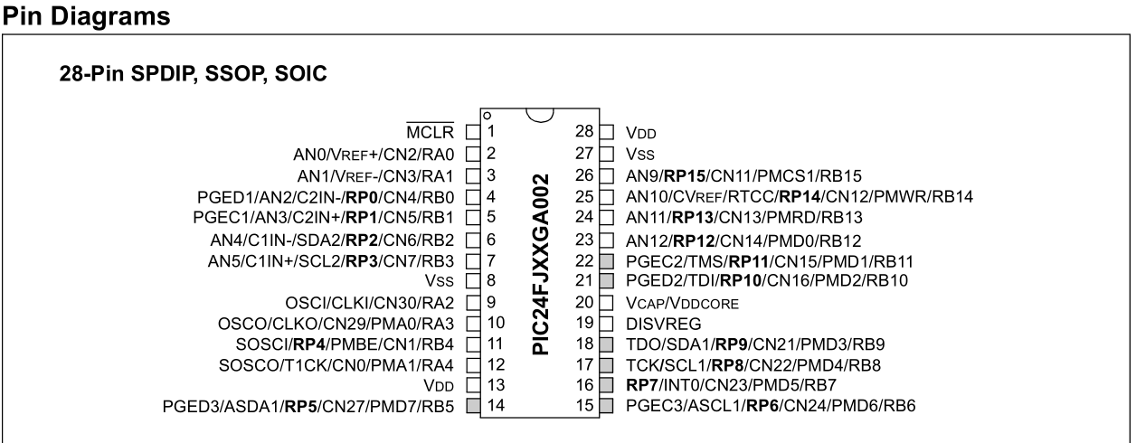
Here's the PIC24FJ64GA004 family pinout again:
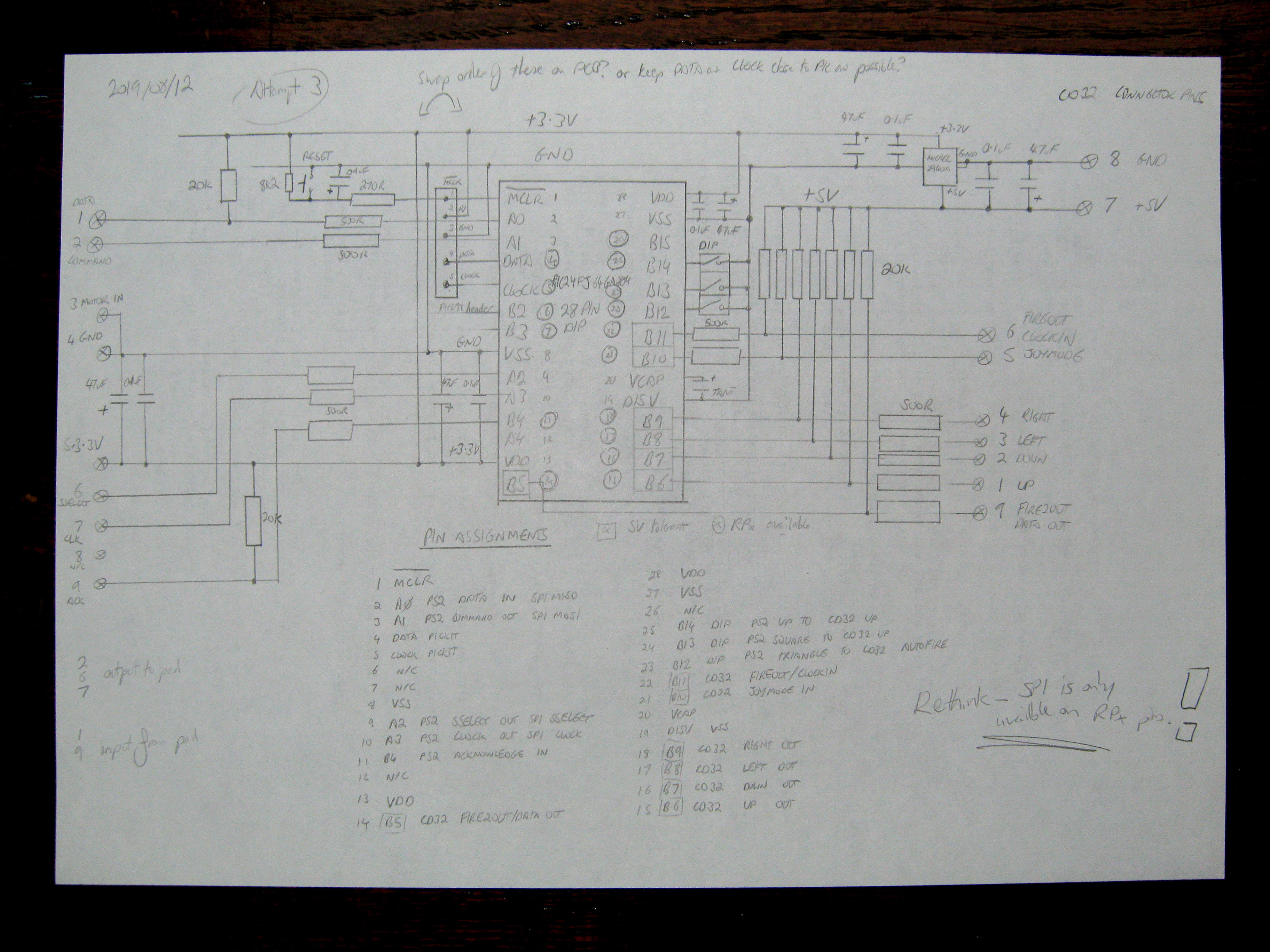
And take a look at my Attempt 3 design:
The circled pin numbers in my design are the ones that are
RPx remappable peripheral pins. I've drawn the PS2 SPI
DATA and PS2 SPI
COMMAND pins connected to pins 2 and 3 on the PIC, which aren't
RPx pins. Oops. I can't use pins 4 or 5 since they're dedicated to the ICSP. I could dual-purpose them, but I'm not entirely confident doing that. I wouldn't want the pad acting strange when the PICkit communicates. In fact, looking back on it now writing this doc, the placements of the other PS2 SPI pins make no sense either. I must've just assumed that they were all
RPx pins. I feel a bit of a lemon drawing in the circles afterwards.
Aside from that error, I've been a bit more courageous with my resistor values, reducing the safeties and weakening the pull-ups, so the Amiga and MCU have more tug over the lines and more current flows. The maximum input current on any GPIO pin on this PIC is 25mA (Section 27.0), which is bucketloads. A 3-circuit DIP switch on the upper right provides some way to configure the device once it's been built, replacing the jumper from the first design. This is for things like Button to Jump, Autofire, etc.
This is why we draw tons and tons of diagrams, and write descriptions of how we expect things to work!